Torchy Oriole Bike Light
I wanted to do some night mountain biking on the moors above my home and for that a light was required. I bought a Torchy Oriole for £40 from Mr. Torchy's shop on eBay based on the strength of some reviews I'd read and the price; £££ of Hope or Exposure lights was a bit out of my budget. I'll be writing a mini review later once I've had more chance to test it in anger.

Torchy Oriole bundle (image courtesy of Mr. Torchy)
The main issues I had was the on/off/mode button was not debounced - switch contact bounce caused multiple button presses to be registered by the controller. So a single button press can cycle through two/three modes. Annoying.
Also, the "strobe" mode on the light was an epilepsy inducing 8-( super bright flashing mode that would only serve to annoy motorists and have no use on the trail. Also annoying.
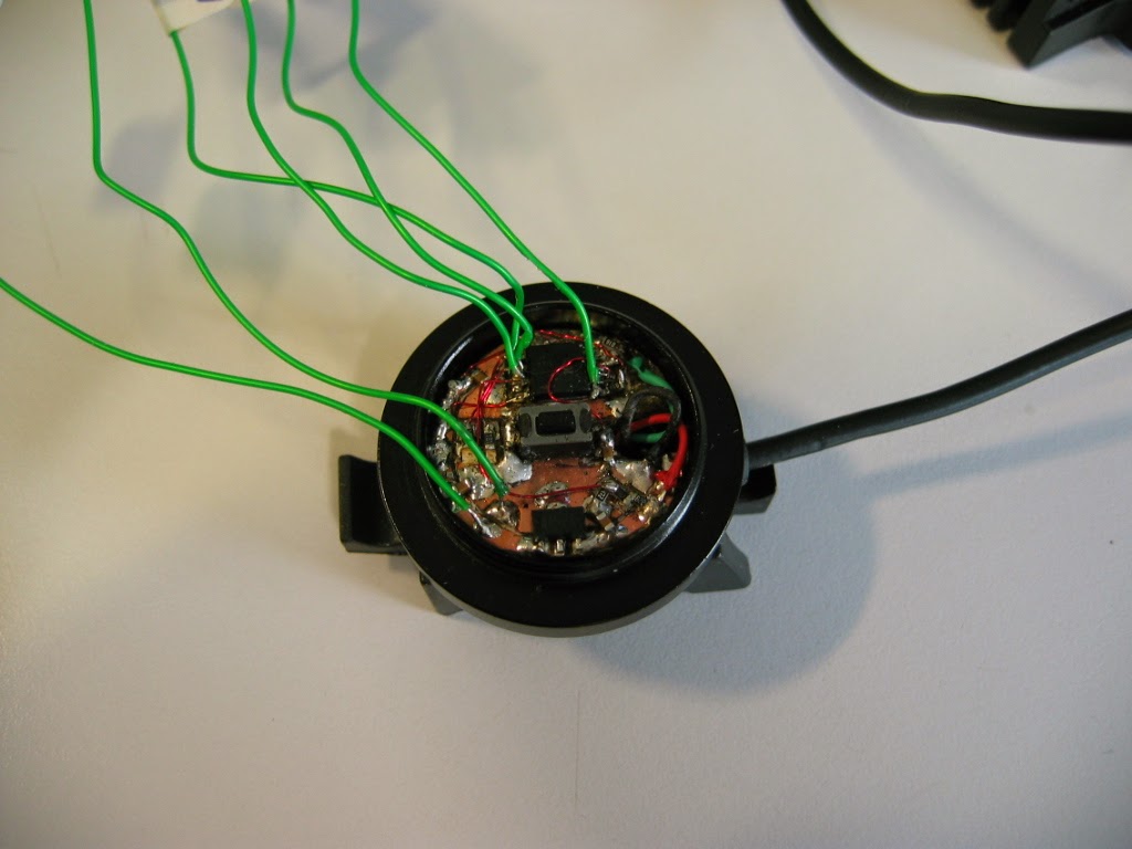
Existing Controller
This PCB was inside the handlebar mounted button. A 2 layer PCB (no insulation between bottom layer and anodised aluminium housing), some kind of micro with the number removed from the top (probably a PIC), 4 LEDs driven direct from the PIC pins (no current limit) for battery level indication, a transistor to buffer the on/off PWM output to the SMPS in the light head and a tantalum capacitor.

Initially I tried to add a capacitor to ground from one of the button pins to debounce the switch but in doing so I managed to break the controller. More annoying. Time to roll my own!
New Controller
Thankfully the control output from the micro to the light head is a standard 3.3V logic PWM signal so making a replacement controller involves no reverse engineering. Spec time:
- Single push button to select modes
- Lighting modes
- 100% constant
- 50% constant
- 15% constant
- 15% constant with a 2Hz, 100ms, 100% flash strobe AKA commuter mode
- Fit into existing button housing
- High and low battery warning LEDs
- A debounced button input
The strobe-plus-steady lighting mode is very effective at catching drivers eye's when commuting; I think Exposure lights have this lighting mode. It has the effect of providing the super birght flash to make you noticed without blinding people whilst providing a steady light so that your speed can be judged more easily.
I've got lots of experience with the Arduino platform which is great for quickly lashing things up but even the smallest Arduino based solution would be too big for this project. So, having designed with Atmel AVR microcontrollers before I chose one of the smallest ones for this job, the ATtiny25. The 2kB of program memory is more than sufficient for this application and an 8 pin SOIC package should fit on the board OK. Programming was handled using the AVRISP MKII and code was written using the excellent Codevision AVR C compiler.

Schematic of the new controller
Surface mount components had to be used to fit everything into the available space which was a bit of a squeeze. I made my own circuit board by taking some copper clad board and hacking grooves in it with a craft knife. Crude but effective.
I used a 78L33 regulator to get the DC supply for the micro because it has inbuilt over current protection and a 30V max input voltage - many smaller regulators only had a 7.5V maximum voltage and could have been damaged by a fully charged battery.
The ATtiny25 can drive up to 40mA direct from the pins, more than enough for an LED. The voltage divider from the battery line was calculated to give 2.56V (same as the internal reference) from a 10V battery (higher than the worst case LiPo voltage for the supplied battery). The actual voltage levels vs battery indicator type were taken from measurements made on the original controller.

Photos

Programming connections were a bit of a nightmare to attach

The finished controller
Everything fitted nicely inside. Cable entry (2 o clock), battery voltage divider (3 o clock), voltage regulator (4 o clock), LEDs, 8 o clock and microcontroller (half past 10). I reused the button from the original controller as it had a small profile and worked with the existing mechanics well. Overall diameter 22mm.

With diffuser in place and button ready to screw on top
Software
The software was crude but effective. I don't do enough coding to write elegant, super efficient code which is why I like Arduino so much as the pre-written functions make life so much easier. As a result delays are brute force for (;;) loops and the debounce code will probably make grown men wince. But it works which is the main thing. Click here if you want to have a look.
The built in PWM mode of timer 1 is used to produce a 120Hz PWM to drive the lamp SMPS controller via the green wire. The controller also steps down the maximum PWM to 15% if the battery voltage goes below 6.7V as a "get you home" mode. The battery voltage monitoring function has some hysteresis in the level thresholds to prevent constant flipping between modes. To make life simpler, the ADC output is only the 8 MSBs of it's 10 bit range so it can be mapped to an unsigned char rather than an int type. This is done by setting the ADLAR bit.
When entering strobe mode, the strobe flashes straight away to provide clear visual feedback that the button press has been registered. Also, when the battery is initially connected the indicator LEDs both light and the main LED pulses up to 15% as a self test of the system.
Conclusion and Possible Improvements
The new controller works great and is a vast improvement on the old one.
I'd be tempted to add a more sophisticated hysteresis function into the battery level monitor as it does trip between "green" and "red" LED states with every strobe pulse when in strobe mode but that's a small complaint.
Also it could benefit from a transistor to isolate the PWM pin from the main LED controller during startup as the LED turns on full brightness until the micro boots up and initialises the outputs correctly. This isn't a massive issue.
Time to get up onto Ilkley Moor on Herman for more of this!

Baht 'at, but with helmet and a reet big lamp!
I'd be tempted to add a more sophisticated hysteresis function into the battery level monitor as it does trip between "green" and "red" LED states with every strobe pulse when in strobe mode but that's a small complaint.
Also it could benefit from a transistor to isolate the PWM pin from the main LED controller during startup as the LED turns on full brightness until the micro boots up and initialises the outputs correctly. This isn't a massive issue.
Time to get up onto Ilkley Moor on Herman for more of this!
Baht 'at, but with helmet and a reet big lamp!
No comments:
Post a Comment